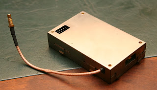
While this worked fine, the local radio amateur electronics recycling team turned up with a high-end oven oscillator board integrated with a 100MHz phase-locked crystal oscillator and a multiplier chain for a 800MHz output. This opened up some possibilities and ideas and warranted the design of a separate complete reference source system. Seems I've lost any unmodified pictures of it separately, it can be seen in later pics.
Ebay provided me with a Jupiter-T GPS module, which has the specialty of having a 10kHz output. There are GPS devices that output 10MHz directly, but the cost was a bit too high. But 10kHz is enough to allow phase locking the oven oscillator to the GPS signal.
As there are no special requirements for the signal speed or phase noise, the PLL can be very simple and have a loop frequency of around 1Hz with a non-critical loop filter. Pictured above is a plug-in board with a 10-output clock buffer, a couple of regulators and a CPLD that contains a clock divider from 10MHz to 10kHz and a phase detector, which together with a simple external RC filter implements the PLL. After an eternity of waiting for the GPS to lock with a weak signal, it showed my spectrum analyzer's internal oven oscillator to have an error of 19Hz at 800MHz.
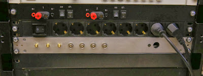
Above pic shows the reference system after integrating the OCXO board and the GPS and PLL boards into a recycled rack enclosure, below a pic of the box integrated into the equipment rack.
Below is the approximate block diagram.


What was the 10-output clock buffer chip used for the original design? Can you share a link to that schematic? Thanks!
VastaaPoistaThe chip was a CDCVF2310, which I happened to have a number of. In hindsight, a linear buffer would probably have been a better choice for the sine shaped output of the OCXO. I should probably post an update for this some day.
PoistaI'm not sure where the schematic is now, anyway I had to hack the design a bit and the schematic was not updated then