For a while I considered using the ARM processor board with a USB connection to the controlling PC (which on retrospect would probably have been the best choice), but I happened to have a Beagleboard Xm board bought as a toy, which happened to have both SPI and I2C buses I'd need to control various hardware modules. The toy project quickly gathered functionality around it.
In the picture above is the connectivity board I made for the Beagleboard. It has a wide-input switch mode regulator that supplies the 5V needed by the Beagleboard, a number of level shifters to shift the Beagleboard 1.8V logic level I/O ports to 3.3V levels, and an RTC as I had some problems getting the one on the Beagleboard to function properly. Also present are a couple of I2C and SPI headers for external connectivity, and a bus switch to double the number of possible SPI devices. The board has its share of bugs and design errors, but I have not yet made an upgrade.
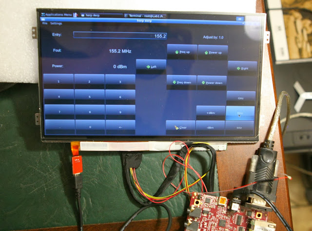
Here's a pic of the Beagleboard, connectivity board, synthesizer and a quick TCXO board that generates the reference for the synthesizer. The tiny SMD trimmer board in the right edge is a brightness adjustment trimmer for a TFT display panel bought from Chalkboard Electronics, a very nice 10" unpackaged panel with a capacitive touch surface and an adapter board to interface directly to the Beagleboard.
At this point I had purchased a 21U 19" rack to house my equipment, and it made sense to integrate the device there. I had no 4U case at hand to attach the screen into, so it is just attached to a front panel, awaiting a separate case or several on the back side of the rack to house the various electronics of the system. The spectrum analyzer is showing the result of a sweep from 137MHz to 3GHz on the synthesizer with a power setting around 10dB below the maximum output. Not very straight line, it would require calibration to level out the response. That has yet to happen...
At this point I was considering a switched chain of multipliers and amplifiers to increase the frequency range, and diode detectors to allow sweeped measurements. It was clear the system would grow in complexity and sophistication, and the only solid part of the design was that it would have to be very modular, with each part adding to the functionality, rather than aiming for some specific totality, or nothing useful would ever get finished...


Ei kommentteja:
Lähetä kommentti